Rigid Flex PCB Design Guidelines
Early in the rigid flex PCB design process, it’s essential to give ample consideration to how choices made in the board design will result in reduced costs while maintaining reliability. Here we’ll lay out the general design principles that should guide a designer of rigid flex PCB’s.
What is a Rigid Flex Board?
A rigid flex board is a hybrid of hardboard and flexible circuits. The manufacturing process resembles that of a traditional hardboard circuit, but some of the layers are flexible circuitry that run all the way through the hardboards. The board fabricator will then add plated through holes to connect layers of rigid circuit to regions of flexible circuit.
These configurations create a rigid flex PCB that can be assembled similarly to hardboards, but also fold to fit into a product with space constraints. They are also suitable for continuously flexing applications – also known as dynamic flex. Well designed, a rigid flex board can withstand hundreds of thousands of flex cycles without failure. In either case, the rigid and flexible substrates form one integrated unit that can be further manipulated into a 3D subassembly.
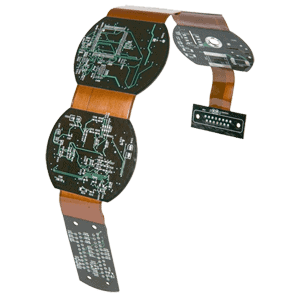
rigid flex PCB
It’s important to differentiate between rigid flex boards and flex boards with stiffeners, which can sometimes be used for similar applications. Stiffeners on flexible circuits do provide some amount of stability for assembly and mechanical purposes. However, flexible circuits with stiffeners are limited in where components can be placed, and ultimately overall component density.
As such, the deciding factor between a flex board with stiffeners and a rigid flex board is whether or not a flexible circuit with stiffeners will provide the PCB designer the component density he/she desires. As the component density increases, flexible circuits with stiffeners reach their limit, and a rigid flex solution becomes much more desirable. Rigid flex boards simplify the assembly process while providing a much higher density of components and circuit routing. If this is not needed, flex boards with stiffeners may be sufficient and will be less expensive as well.
Rigid flex PCB cost quite a bit more than comparable hardboards, and are usually two to three times the cost of a flexible circuit with stiffener. However, the increased cost is justified when it comes to specific applications and environments, such as:
High-reliability applications. If an assembly will be exposed to excessive or repeated shock, or high vibration environments, connectors with flexible cables are more likely to fail. Rigid flex PCBs provide great reliability even when subjected to extreme vibration and shock applications.
High-density applications. Within a small enclosure, it’s sometimes impossible to accommodate all the cables and connectors that an electronic PCB design would require. Rigid flex boards can fold into very small profiles, offering substantial space savings in these instances.
Five or more rigid boards. If your application will ultimately involve five or more rigid boards connected to one another with flex cables, an integrated rigid flex solution is often the optimal and more cost-effective choice.
Rigid Flex Design Guidelines
Broadly speaking, a rigid flex design will closely resemble a hardboard design, with the flexible layers fully extending into the rigid areas of the board. Similarly to hardboard layouts, a rigid flex fabrication package will include Gerber layers, along with drill files, solder mask layers, nomenclature, perimeter/rout files, coverlayer, etc.
However, there are some key differences between the fabrication packages for rigid flex PCB’s and hardboard applications:
A rigid flex print generally has many more dimensions on it, and should carefully define the requirements, as these boards are generally used in 3D applications. It should also accurately define the rigid to flex transition areas, as these are not always apparent when viewing the Gerber layers alone.
The material layup in rigid flex boards is critical, and should be worked out in collaboration with your fabricator. Your fabricator can help you make the right choices in materials based your requirements such as UL flammability rating, minimum bend radii required, mechanical considerations, impedance control on both flex and rigid layers, RoHS certification, lead free assembly compatibility, and other considerations.
Rigid flex boards usually require additional layers in the Gerber files. Layers 1 and X will have solder mask layers, but you will also need artwork layers that define the coverlayer and bondply sections (if required) of the board, and how much each go into the hardboards. IPC 2223 recommends 0.100″ but your fabricator may be able to accommodate less than that.
The IPC-2223 Sectional Design Standard for Flexible Printed Boards is an excellent resource for wise practices in both flexible circuit and rigid flex circuit design. An electronic download of the IPC 2223 can be purchased here.
Material Layup Considerations
Rigid flex material layups heavily influence cost, manufacturability, and final PCB performance, so it’s essential to spend time determining the ideal material set. For instance, controlled impedance, resistance, and current-carrying requirements are all important considerations that affect both copper weights and material selection.
A PCB designer should collaborate with their board fabricator to discuss these variables, so that the resulting design complies with all signal integrity requirements. Once the designer has performed initial calculations, the fabricator can verify them, and provide a more accurate modeling of the impedance characteristics of the board, and material set required to achieve those values.
If impedance characteristics are not that critical, our you are looking for the lowest cost, most stable rigid flex design suggestions, check out our Rigid Flex Valu Builds. The Rigid Flex Valu Build program offers the lowest overall material costs for rigid flex design, while also providing a very safe starting point for designers who are new to rigid flex design.
If you would like to get a quick estimate on how much your rigid flex design might cost, try our Rigid Flex Cost Estimator. The rigid flex cost estimator will take your requirements and will give you an estimated cost for low level production quantities. It is a great starting point to see if your design is economically feasible with your program requirements.
The rigid sections of rigid flex boards are usually 20 layers or less. There are times when they have more, but usually more than twenty layers is pretty rare. The hard board sections don’t all have to have the same layer count. For example, you could have one rigid section with 16 layers of circuitry and one with 12. As long as the material layup is similar for each and the boards have the same overall thickness, there will be no manufacturing issues. Occasionally, a design may use hardboards that differ in thickness, but such configurations are substantially more difficult to manufacture, and other options should be considered.
The flexible sections of rigid flex boards are usually one (singlet), two (doublet), three (triplet) or four layers (quad construction). There are times when a designer needs more than four layers across the flexible sections of the board, but are almost always unbonded. Bonded flex sections that have more than four layers can be very resistant to bending and or flexing. Copper weights on the flexible layers of the rigid flex boards are most commonly half and one-ounce weights. Occasionally the electrical demand requires two-ounce weights. In those instances, the designer should work very closely with their fabricator to choose the correct no flow prepreg, to adequately fill the thicker circuits in the hardboards. No flow prepreg, by design, does not like to flow and two-ounce circuitry can present some challenges. Three-ounce copper weight is rarely used, and can present substantial issues in manufacturing for the same reason.
Rigid Flex PCBs at Printed Circuit Boards
Here we’ve provided an overview of rigid flex PCB design considerations and how to ensure that your design will be successful. For more thorough coverage of this topic, we invite you to download our latest eBook, “Rigid Flex PCB Design and Installation.“ Additional resources are available on our literature page, including our quality manual.
At pcbsky, we manufacture rigid flex PCB circuits based on your exact specifications, and we aim to provide all the resources you need to help you optimize your PCB as early in the process as possible. To learn more about rigid flex PCB designs or about our capabilities and services, contact the PCBSKY team today.

This comment has been removed by a blog administrator.
ReplyDeleteThis comment has been removed by a blog administrator.
ReplyDeleteThis comment has been removed by a blog administrator.
ReplyDeleteThis comment has been removed by a blog administrator.
ReplyDeleteThis comment has been removed by a blog administrator.
ReplyDelete