Posts

Showing posts from October, 2020

What is ENIG Plating?

Image
  ENIG (Electroless Nickel Immersion Gold)   is a surface plating that is applied over the copper pads on a Printed Circuit Board to protect them from corrosion and other abnormalities. Initially, the copper pad is covered by a   Nickel (Ni)   layer followed by a thin immersion   Gold (Au)   layer. ENIG provides good oxidation resistance, excellent surface planarity and allows for easy soldering which results in excellent electrical performance of the PCB board. ENIG is RoHS compliant is therefore one of the most used PCB surface finishes even though it is more complex and expensive when compared to other PCB plating process like  HASL . ENIG is a two-layer metallic coating –  Nickle  is the barrier to the copper pad and is also the materials to which the components are soldered.  Gold  on the other hand protects the Nickle during storage and also provides low contact resistance. Typical Nickle thickness varies from  4 – 7 µm and Gold thickness varies from 0.05 – 0 23 µm.  ENIG require

PCB should use FR4 material if selected.

Image
 A Guide to FR4: When Can You Use It and When Can You Not Most electrical engineers and individuals involved with printed circuit boards are familiar with the material FR4. FR4 is the backbone material upon which most rigid circuit boards are built. However, many are unaware of what FR4 is, let alone why it is the most popular PCB base. Read on to learn more about FR4 printed circuit boards, such as what they are, why they are so popular and how FR4 PCB specifications compare to other options within the industry. What Is FR4 Material?  FR4, also written as FR-4, is both a name and a rating. The name is applied to the fiberglass-reinforced epoxy-laminated sheets used in printed circuit board manufacturing. However, the name also functions as a grade used to rate epoxy laminate sheets. The designation essentially indicates the base quality of a laminate sheet, meaning a variety of sheet materials and designs fall under the FR4 rating. The “FR” in the name stands for flame retardant, whil

Wave Soldering vs. Reflow Soldering

 Soldering is a huge part of the printed circuit board design process. The only reliable way to get your circuits to stick to your board and stay there is by soldering them on. Without soldering, there are no printed circuit boards. But not all types of soldering are created equal, and it can be important to differentiate between the different types of PCBs. There are two main types of soldering for PCBs: wave soldering and reflow soldering. What is the difference between the two, and how do you know which type of soldering to use in which circumstances? What Is Wave Soldering? Wave soldering is a bulk soldering process that enables one to manufacture many circuit boards in a very short amount of time. It works by passing each circuit board over a pan of molten solder. A pump in the pan creates a “wave” of solder that washes over the board, soldering the components to the board. The PCB then receives a water spray or air blowing to safely cool it and fix the parts in place. Proper temp

What is a Rigid Flex PCBs?

Image
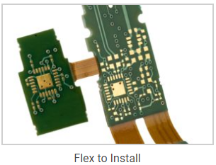
A rigid flex printed circuit board (PCB) is a hybrid circuit board design that integrates elements from both hardboard and flexible circuits. Rigid flex PCBs are rigid at some points on the board and flexible at others. Because of this, rigid flex circuits can be folded or continuously flexed while maintaining the shape of areas that need extra support. The circuits are typically multi-layered and are comprised of flexible circuit substrates joined with rigid boards. The flexible layers are buried internally and completely penetrate the rigid sections of the PCB. One of the key benefits of a rigid flex PCB is its slim profile. The standard dielectric in flexible circuits is .001 – .002”, making it a great choice for ultra thin—and ultra light—packaging needs. Adhesiveless laminates, HDI, and thin copper layers make it ideal for fine line technology, giving you the smallest, thinnest, and lightest solution for your circuit designs. Rigid Flex Types Rigid flex PCBs support two primary ap

RF PCB – Radio Frequency Printed Circuit Boards

Image
  Radio frequency printed circuit boards ( RF PCBs ) are an exciting, fast growing sector of the PCB manufacturing industry. They are also incredibly complex with a dizzying range of options. The engineers at San Francisco Circuits can assist you with every step of the fabrication and assembly process, including material selection and key RF PCB manufacturing challenges to be aware of. What is an RF Circuit Board? In general terms, the PCB industry considers an RF circuit board to be any high frequency PCB that operates above 100MHz. Within the radio frequency class, anything above 2GHz is a Microwave PCB. What is a Microwave PCB? The main difference between RF circuit boards and Microwave PCBs is in the radio frequency in which they operate. Microwave PCBs are classified as any RF circuit board operating above 2GHz. RF circuit boards and Microwave PCBs are used for communication signals in any application that requires receiving and transmitting radio signals. For example, some common

PCB Surface Finishes Comparison: HASL LF, OSP, & ENIG

 A PCB surface finish is a coating between a component and a bare board PCB. It is applied for two basic reasons: to ensure solderability, and to protect exposed copper circuitry. As there are many types of surface finishes, selecting the right one is no easy task, especially as surface mounts have become more complex and regulations such as RoHS and WEEE have changed industry standards. Criteria Consider the following: Lead vs. Lead free* Component Type* Cost * Reworkability Productivity Environment HASL and lead-free HASL For decades HASL was one of the most popular surface finish choices. Yet, in recent years, manufacturers have realized its limitations. While a surface finish may be low cost and robust, fundamental changes in the PCB industry—namely, the rise complex surface mount technology—have exposed its shortcomings. HASL leaves uneven surfaces and is not suitable for fine pitch components. Although it does come in lead-free, there are other lead-free options which will like

Rogers PCB fab

Image
  Rogers PCB laminate are the raw materials we have chosen to one of the best. We have prepared a sufficient conventional Rogers PCB laminate stock, that can on time delivery to your Rogers PCB. ROGERS 4003C and ROGERS 4350B provide a more cost-effective and processable choice of high frequency materials than PTFE due to their excellent low dielectric loss characteristics, and are widely used in cellular base station antennas and power amplifiers, microwave point-to-point connectivity (P2P), automotive radar and sensors, radio frequency identification (RFID), high frequency head (LNB) of direct broadcast satellites, and other fields. Besides, the thermal expansion coefficient of X and Y axis is similar to the copper, and the expansion coefficient of Z axis is much lower than FR4 (46ppm/oC), and has a high Tg value (>280oC), which guarantees the good dimensional stability and high reliability of the whole product in the PCB process and assemble, and it will bring more benefits to th